When developing early prototypes, it is crucial to have some freedom. That allows engineers to test different layouts, change component positions and adjust flow paths as the assay, process or device concept evolves. Tubing provides that freedom. It is visible, accessible and quick to change.
But a layout that works on a bench can be less flexible inside a compact device. More channels, functions, valves, sensors and interfaces have to fit into a smaller space. Routing starts to get in the way of usability, cleanability and production repeatability.
The problem increases in stages:
One added function needs another tube, fitting or connector.
One design change shifts the routing and creates new bending radii or access issues.
One extra interface creates another potential leakage point.
One manual step adds another potential variation during assembly.
At first, each change looks manageable. But when put together, they can create a fluid path that becomes hard to assemble, hard to clean and hard to reproduce. That is the point when routing stops being a layout task and becomes an architectural issue.
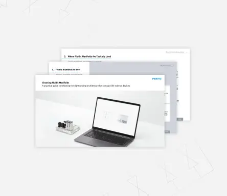
This blog gives you the first points to compare. The solution guide takes you to the next step and helps your team review tubing, manifold technologies, bonding methods, materials, and supplier models before you lock in a design path.
Use it as a practical filter for your next internal review or supplier discussion. You will get clearer questions, a better overview of the trade-offs and a more structured basis for deciding which fluidic architecture should be evaluated more thoroughly.
Compare your optionsToo many fluidic connections do not usually create an obvious problem straightaway. More often, they add small variations that are harder to manage over time. A fitting here, a longer tube there, a route around a sensor, a tight space behind a valve. Each decision can make sense on its own, but the combined effect can make the design less reliable and harder to replicate.
Watch for these risks:
- Leakage risk: each manual connection can add another potential leakage point
- Dead volume: unused internal spaces can affect reagent use, sample handling and response time
- Trapped bubbles: complex paths and transitions can hinder flow consistency and lead to unclear results
- Cross-contamination: difficult-to-clean areas can increase carryover risk between samples or media
- Assembly errors: similar tubes, repeated connections and limited access can increase fault liability
- Service effort: dense routing can slow down inspection, replacement or maintenance
- Footprint pressure: tubing can take up space that should be used for device functionality, usability or miniaturisation
In diagnostics and compact life science devices, these issues can affect engineering effort. More importantly, they can influence test reliability, user confidence and production readiness. The device may still work, but that does not mean the architecture is truly functional.
A problem in the fluidic architecture often leads to several small frustrations. No one symptom on its own means the design needs a new route. But a pattern should indicate that a closer review is necessary.
Use these questions as a first diagnostic check:
Does routing take more space than expected?
If tubes and fittings dominate the internal layout, miniaturisation may be harder, especially when new functions are added.
Do test results vary without a clear reason?
Leakages, trapped bubbles, dead volume or an inconsistent liquid flow can create noise that looks like assay or process instability.
Does cleaning take too much effort?
If cleanability depends on complex flushing routines or manual access, the fluid path may not support future validation needs.
Does replication slow down because of routing changes?
If the routing needs to be redesigned every time a component is moved, the architecture may not be stable enough to be scaled up.
Is assembly becoming too dependent on individual skills?
Manual tubing layouts can be difficult to replicate when production needs consistency.
Are valves, sensors or pressure control components difficult to integrate cleanly?
If components are placed around the fluid path instead of inside a coherent system, the layout may hamper the next design step.
A more in-depth review looks at the full fluidic architecture: how media flows, cleans and exits the system, and how the route supports assembly, service and production. This helps the team move beyond finding short-term fixes for individual issues.
That means checking the pressure or channel size, where fluids change direction, which interfaces add avoidable leakage risks, and where dead volume or trapped bubbles could affect the repeatability of results. It also means looking at which sections are difficult to clean, inspect or service, and which functions need to have integrated valves and sensors.
The aim is to define the requirements of the fluid path before the team compares technologies, suppliers or integration options. That gives start-up OEMs, established OEMs and engineering service providers a clearer basis for the next design decision.
Once the requirements are clearly defined, the next step is not to select a technology straight away. It is to collect all the information that makes a useful comparison of the different technologies possible: media, pressure and flow range, channel geometry, material compatibility, cleanability needs, integration points and production outlook.
This allows the team to check whether the issue is still manageable with routing improvements, or whether the fluidic architecture needs a more structured approach before the project is progressed towards validation and tooling or moved into production.
The team can then compare possible routing approaches. That may include an improved tubing layout, a dedicated fluidic manifold or a broader integrated fluidic solution. For teams that see compact internal channels and clean material bonding as relevant, an overview of diffusion bonded manifolds can help decide whether this option should be included in the comparison. The value lies in comparing options against the real constraints of the device, not against a generic preference for one technology.
Do you want to discuss your fluidic design approach or start shaping the project before the layout is defined? Share your current requirements, open questions or early concept with us. We can help clarify which architecture, material options and integration level should be reviewed first.