Autonomous pressure and vacuum generation
When designing devices for liquids operated by compressed air, external compressed air sources must always be taken into account, as liquid handling systems usually require a constant air supply. The most common supply is via a wall connection; however, this restricts the flexibility of the system. And having to retrofit air ducts would lead to higher costs.
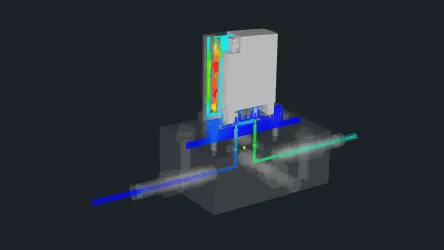
That is why Festo has developed a module for generating pressure and vacuum that does away with the need for compressed air supply via supply lines. This compact submodule is an integral part of the liquid handling system. The generator builds up a specific pressure and vacuum. If the values fall below a specific threshold value, the supply is activated and the pressure and vacuum built up again. This is done using various sensors, a pump and a distributor.
Multiple dosing with reservoir and scale
Festo designed a special manifold duct plate with a reservoir for the dispense head VTOE for multiple dosing with maximum repetition accuracy. This makes it possible to draw in up to 2 ml of liquid. The dispense head works in conjunction with a scale positioned under the microwell plate, thus creating a closed feedback circuit for the dosing process. By having continuous feedback, the opening time of the pneumatic valve can be fine-tuned to achieve accurate dosing volumes.
After drawing in the required volume for the total dosage, the liquid is dispensed into each well in three injection phases. During the first and longest phase, most of the liquid is dispensed. The second injection phase is shorter and gets closer to the required volume. The last injection is very short in order to achieve the exact filling quantity. Exact means that accuracies better than 1% CV can be achieved.
Easy to adjust and operate
This solution includes a graphical user interface (GUI). It enables laboratories to carry out tests to meet individual requirements without having to reset the system every time. For example, the GUI allows the user to select from which vial to aspirate, how much fluid is dispensed into each well of a microwell plate, and how many wells are to be filled in a particular row. While the liquid is being dispensed, the GUI provides a live display of the scale to indicate the amount of liquid dispensed. The amount of liquid is used to calculate the average mass and the coefficient of variation (CV) of the dosage.
The GUI gives the user access to additional functions such as rinsing the liquid in the manifold duct plate until only air is left, or cleaning the manifold duct plate by drawing in and rinsing using a cleaning solution.
See innovative liquid handling in action
The system described in this article is the result of cooperation between Festo TEC Boston, Festo LifeTech's development center in North America, and Festo's headquarters in Germany. In the video, you can see all the submodules in action. A compact planar surface gantry EXCM with parallel kinematic actuator concept ensures fast and precise movements.
Outlook
The team at TEC Boston is already planning the next step: a module for generating pressure and vacuum that can be installed in line with the plug-and-play principle and will therefore significantly reduce installation time.
Our free Liquid Handling resources:
Do you need to know the basics of designing a pneumatic dispensing system? Upgrade your pneumatics know-how to reach your optimum liquid handling throughput. Download our seven page whitepaper.
How to set up your liquid handling system in four steps! Remove the risk of making costly mistakes with automated liquid dispensing. Download our four step guide here.


