


 24 / 40

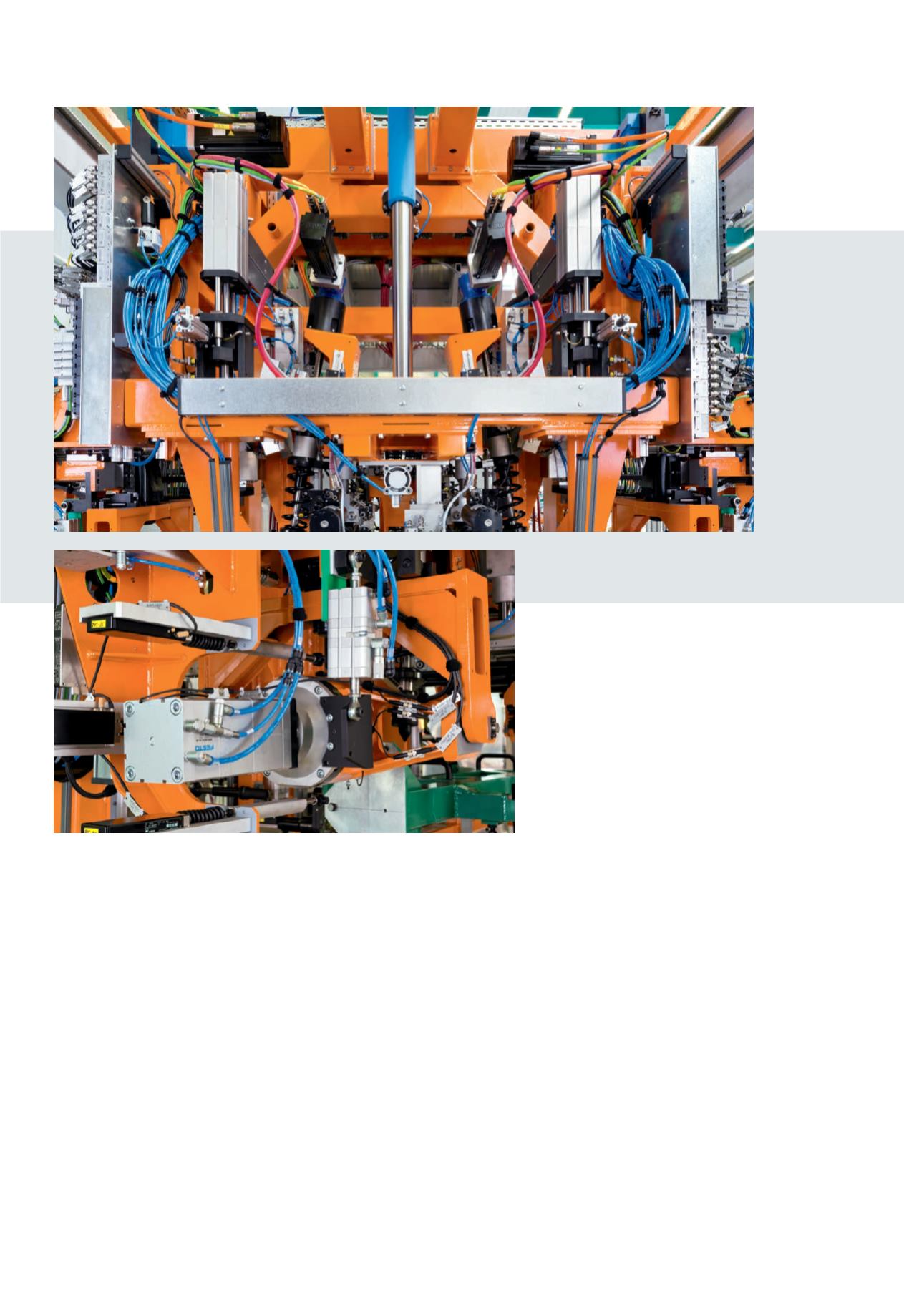
(A) ADNH high force cylinders
clamp the axle in the system as if
it were screwed onto the vehicle.
(B) Powerful argument:
the advantage
of the high force cylinders lies in the
sequence of up to four cylinders with
the same piston diameter and stroke.
(A)
(B)
Securely clamped
Integrated directly in the production
process of the car manufacturer, linear
conveyor technology transports the axle
on a workpiece carrier through the
machine in either a longitudinal or a
transverse direction. A lifting frame that
can be lowered directly above the axle
holds all of the Festo components and the
tools for adjusting track and camber. After
the axle is clamped, counterholders
swivel under the subframe mounts of the
axle, and later provide the attachment
points for the car body. ADNH high force
cylinders with a piston diameter of 100
mm clamp the axle at four positions as
accurately as if it were screwed onto the
vehicle. The advantage of the ADNH high
force cylinders is in the series connection
of two, three or four cylinders with the
same piston diameter and stroke. This
means that, compared to a conventional
cylinder, the force can be doubled, tripled
or even quadrupled during the advance
stroke. A Festo SMAT sensor on a guide
unit detects the level of the wheel hub.
The height at which a slide unit must move
to the axle can thus be determined.
Fast adjustment
In the next step, grippers driven by ADNH
high force cylinders clamp themselves to
the hubs. Spring replacement devices
actuated by electric motors then drive
against the axle and automatically locate
the positions where the springs will later
sit.
Next, the axle is pulsed under load to
achieve the setting behaviour on the
rubber mountings and joints. The axle is
then moved to the K0 position. This is the
ideal position of the axle and corresponds
to the normal load, when the vehicle is
loaded with a defined weight. The track
and camber are measured in this position,
with a pneumatic cylinder moving directly
to the brake disc. The adjusting screws are
located independently using track and
camber screwdrivers that are also supplied