
Proportional pressure regulation
Please sign in to see prices or request test licenses
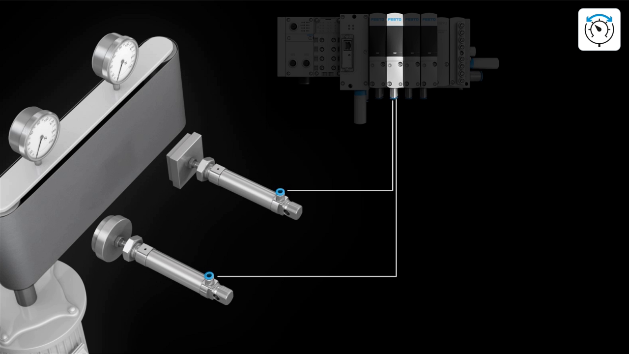
With the Motion App „Proportional pressure regulation“ there are two pressure regulators per valve slice at the two valve outlets which can be used to regulate pressures independently of each other. The integrated sensors precisely monitor the pressure. Only the internal pressure sensors (connections 1, 2, 3, 4) will be used for closed-loop control. As a user, you do not need to submit any details about the system, such as volume or tubing.
This Motion App is also suitable for regulating vacuum applications. For vacuum applications, you can also connect the vacuum to duct 3 of the Festo Motion Terminal. You can simultaneously connect pressure at duct 1 of the Festo Motion Terminal, for example for an ejector pulse. The possible area of application covers pressure control for volume, force control for the known effective area, the activation of process valves and vacuum control with regulated ejector pulse.
When using the Motion Apps at the same time, you have to order exactly the right number of Motion Apps that you need on the Festo Motion Terminal VTEM.
- Pressure:
- -0.9 … +8 bar
- Minimum volume:
- 50 ml
- Maximum volume:
- 2 l (larger volumes can also be regulated, however the valve does restrict the flow rate)
- Specifications in the Motion App and via the PLC:
- Setpoint pressure at duct 2
- Setpoint pressure at duct 4
- Feedback to the controller:
- Actual pressure at duct 2
- Actual pressure at duct 4
- Control characteristics:
- C1: Small volume (≥0.05 l; ≤0.1 l) The control characteristic C1 can be used for all volumes. However, this can be very slow for larger volumes.
- C2: Medium volume (> 0.1 l; < 1 l)
- C3: Large volume (≥1 l)
- CS: Customer-specific setting. The parameters of the controller can be set directly using WebConfig:
- P share = Proportional amplification factor for the difference between setpoint and actual pressures
- I share = Amplification factor for the sum of deviations between setpoint and actual pressure
- TF= Time constants for filtering the internal pressure sensor signal
- All parameters can be saved in the controller and transferred to the PLC via the transfer channel and saved. Which characteristics provide the best results for the user depends on various factors and cannot be clearly determined without knowing the customer's application. The main criterion is the size of the volume.
- The pressure regulator may fluctuate. In this case, you should defer to different pressure regulation characteristics. The first reference point is the volume
- Notes:
- A filter must be installed upstream of valves operated in vacuum mode. This prevents any foreign matter in the intake air getting into the valve, e.g. when operating a suction cup.
- When using internal pilot air supply, the necessary minimum pressure (3 bar) in duct 1 must be maintained.
- The sensors are designed so they are protected against contamination.
- Both the supply pressure at port 1 and the exhaust pressure at port 3 are detected. If a vacuum is connected to port 3, the current low pressure value will be determined.
- When using tubing PUN4, the control characteristic C1 should be selected.
- Zero volume (clogged-up valve outlet): best with CS setting, with control characteristic C1 a stable control behavior with overshoot can be achieved.
- If the pressure setpoint specification for the valve outlet is greater than the supply pressure determined internally, the setpoint value of the internal pressure will be restricted to the supply pressure determined internally.
- If the pressure setpoint specification for a valve outlet is less than the exhaust pressure of +0.1 bar, this outlet will be regulated and fully exhausted.
- Static characteristic values (according to FN 942030) valid from -0.9 … 7 bar:
- Linearity error in the range of 5% ... 95% setpoint value under nominal conditions, based on the ideal characteristic curve: 170 mbar
- Repetition accuracy in the range of 5% ... 95% setpoint value under nominal conditions: 80 mbar
- Max. hysteresis in the range of 5% ... 95% setpoint value under nominal conditions: 80 mbar
- Overall accuracy in the range of 5% ... 95% setpoint value under nominal conditions: 210 mbar
- Response sensitivity in the range of 5% ... 95% setpoint value under nominal conditions: 80 mbar
- Max. temperature error over the entire T-range in addition to overall accuracy: ± 50 mbar
- Zero point suppression:
- Setpoint value less than 100 mbar over exhaust pressure--> exhaust
- Setpoint value 120 mbar or more over exhaust pressure--> control active
- Dynamic characteristic values (according to FN 942030) valid from 0 … 7 bar:
- Recovery time (tubing PUN 8, 2 m, volume 0.1 l Setpoint value jump 25% 75% 25%, control characteristic C1):
- <1 s
- Permitted overshoot with suddenly changing setpoint values (volume 0.1 l at the valve outlet, control characteristic C1):
- <1% FS


